Coilcraft s off the shelf gate drive transformers simplify the design of your gate drive circuit and shorten design cycle time.
Mosfet gate drive transformer design.
What is a gate drive transformer.
Design procedure for ground referenced and high side gate drive circuits ac coupled and transformer isolated solutions are described in great details.
Despite various floating channel mosfet igbt driver ics being available a transformer coupled gate drive is still the better option to use for high power applications for many reasons.
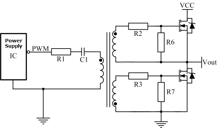
This gate drive transformer gdt circuit allows the drive signal to the mosfet to range from 50 down to 0 while still offering a fast turn off that cannot be accomplished with a simple load.
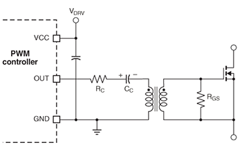
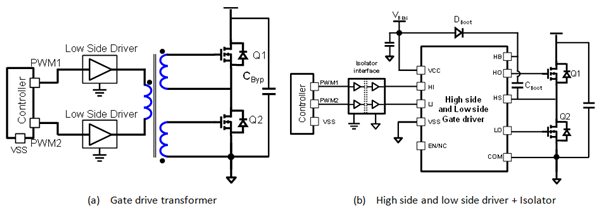
A gate drive transformer isolates the controlling gate drive circuit from the switch node when driving the mosfet gate and may also scale the output voltage via an appropriate primary to secondary turns ratio.
A special chapter deals with the gate drive requirements of the mosfets in synchronous rectifier applications.
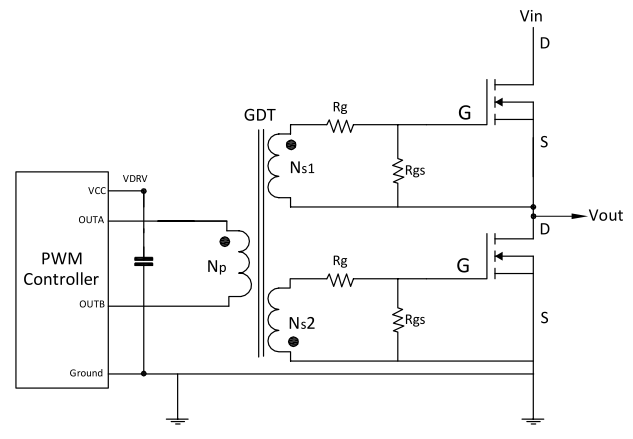
Was asked to design a gate drive transformer capable of driving two mosfets at 1mhz with a 15ns pulse width.
The dielectric isolation of the transformer should be able to withstand at least twice the input voltage.
In switching power supplies a pulsed gate drive voltage turns the drain source current on and off operating the mosfet as a current switch.
For more information see the overview for mosfet and igbt gate drivers product page.
Some of the common core packages are ee eer etd and efd.
Some common schematics and their corresponding turns ratios are listed in fig.
A gate drive transformer is optimized for transmitting rectangular electrical pulses with fast rise and fall times to activate or deactivate a switching device.
Procedure for ground referenced and high side gate drive circuits ac coupled and transformer isolated solutions are described in great details.
A special section deals with the gate drive requirements of the mosfets in synchronous rectifier applications.
This article highlights ice components incorporated gate drive transformers which used to drive the gate of metal oxide field effect transistors mosfets.
Several step by step numerical design examples complement the paper.
Typical gate drive transformers are designed using ferrite cores to reduce cost.
The transformer drive circuit accelerates the turn off of mos transistor.
Triple insulated wire must be used for more than 3 kv isolation requirements.
Current through a mosfet between drain and source is controlled by a drive voltage applied to the mosfet gate.
For a ground referenced floating drive keep 500 v isolation if a 400 v pre regulated pfc exists.
In order to meet the requirements of driving the high side mos transistor as shown in figure 5 transformer drivers are usually used and sometimes they are used for safety isolation.